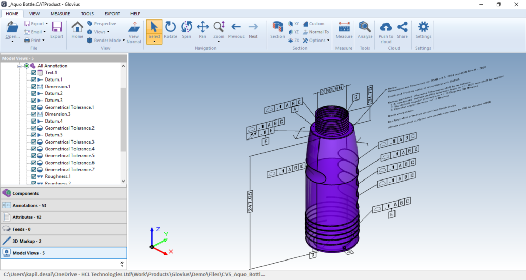
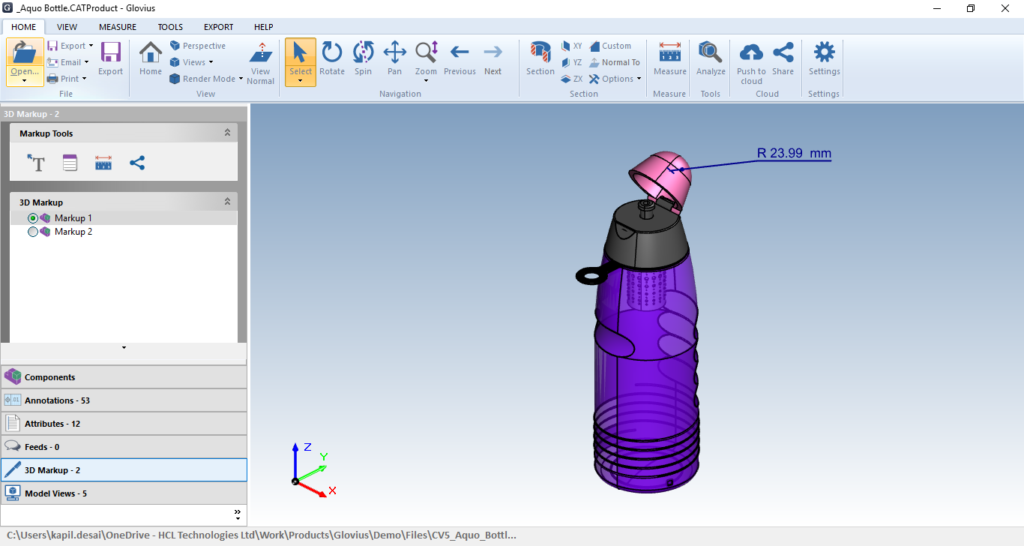
UI Overview
Glovius is a modern CAD viewer for Windows. It’s easy to use and simple interface is ideal for non designers. View 3D files from popular CAD formats with Glovius. Navigate, Analyze, Measure, Section, Compare and Export with Glovius.
Glovius Ribbon Elements
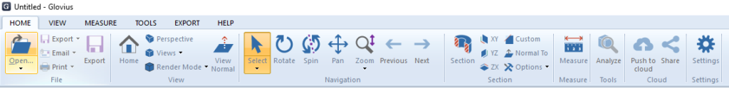
Home
- File
Open – Open 3D CAD file
Export – Export CAD file to another format
Email – Create a screenshot and share
Print – Print the active document - View
Home – Set the view to default orientation
Perspective – Set perspective projection
Views – Set six standard and isometric view
Render Mode – Set Shaded Wireframe, Shaded and Wireframe modes
View Normal – Click to view normal at the point - Navigation
Select – Click entity to select
Select Box – Select components in the specified box
Rotate – Rotate the component
Spin – Select a point and rotate the component along the specific axis
Pan – Pan the component
Zoom – Zoom In/Out of the component
Previous and Next – Go to previous and next view - Section
Section – Take a section along the axes
XY – Take a section along XY plane
YZ – Take a section along YZ plane
ZX – Take a section along ZX plane
Custom – Take a section plane along a plane face
Normal To – View normal to active clipping plane
Options –
Plane – Toggle to show and hide section plane
Cap – Toggle to fill open edges at section plane
Flip – Toggle to flip the section plane direction
Outline – Toggle to show outline of section
Hatching – Cross section hatching - Measure – Select any two entities and measure the linear, angular or radial dimensions.
Tools
Analyze – Select a component to get quick overview.
Cloud
Push to cloud – Push your file to your Glovius cloud account.
Share – Share your file
Settings
General –
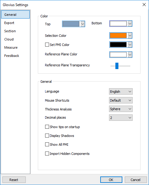
Color
Top and Bottom – Change background color of Glovius
Selection Color – Change selection color
Set PMI Color – Change color for PMI available in file
Reference Plane Color – Change color for reference plane available in file
Reference Plane Transparency – Change transparency of reference plane available in file
General
- Language – Change GUI language of Glovius. Glovius support following languages –
English, French, German, Korean, Japanese, Chinese, Portuguese and Spanish. - Mouse Shortcuts – Change mouse shortcuts similar to CAD like CATIA, Creo, Inventor, NX, SolidWorks, Solid Edge.
- Thickness Analysis – Change thickness analysis method to Ray or Sphere.
- Decimal Place – Set accuracy of measurement by changing decimal place upto 5.
- Show tips on startup – Show Glovius tips on startup
- Display Shadows – Toggle to show shadows for component
- Show All PMI – Toggle to show PMI available in file
- Import Hidden Components – Open hidden components in Glovius from assembly file
Export
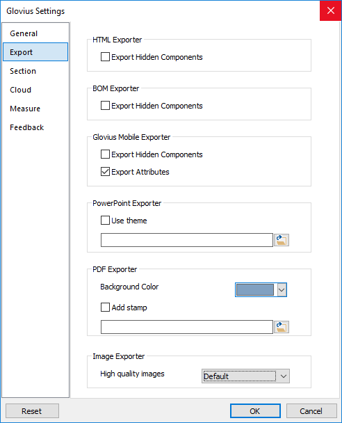
Glovius Mobile Exporter
- Export Hidden Components – Export hidden components in Glovius mobile format from assembly file
- Export Attributes – Export attributes from model to Glovius mobile format
Image Exporter
High Quality Images – Export high quality images
PowerPoint Exporter
Use Theme – Change theme for PPT export
BOM Exporter
Export Hidden Components – Enable export for BOM for hidden components from assembly file
HTML Exporter
Export Hidden Components – Enable export for hidden components from assembly file in HTML
PDF Exporter
Background Color – Change background color while exporting the file to 3D PDF
Add Stamp – Add stamp to exported 3D PDF fil
Section
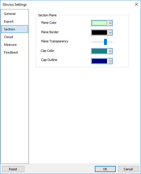
- Plane Color – Change section plane color
- Plane Border – Change section plane
- Plane Transparency – Set section plane transparency
- Cap Color – Change section cap color
- Cap Outline – Toggle section cap outline
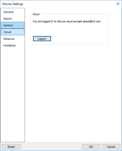
Cloud
Measure
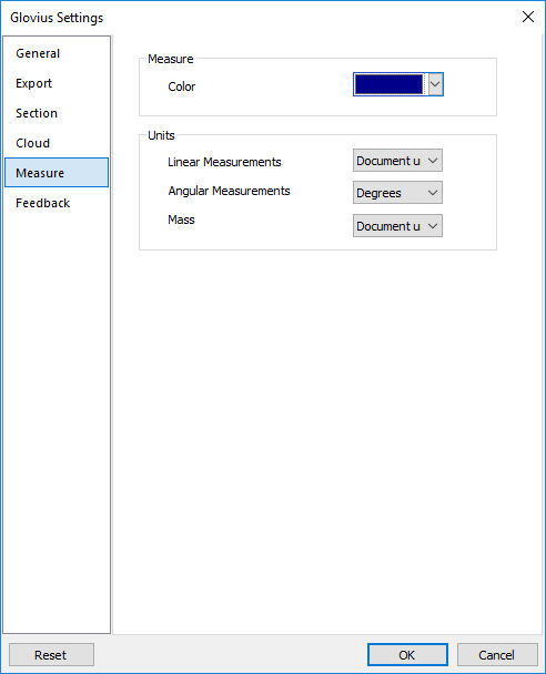
Color
Change dimension line color
Units
- Linear Measurements – Change unit for linear dimensions to millimeters, centimeter, inches, feet, meters
- Angular Measurements – Change unit for angular dimensions to degrees and radians
- Mass – Change unit for mass to kilograms, grams, pounds, ounces
Feedback
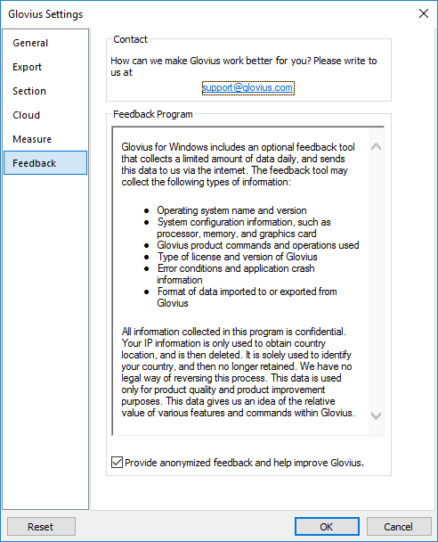
Opt in to send limited amount of data to Glovius
This data is used only for product quality and product improvement purposes
Reset
Reset glovius options to default
View
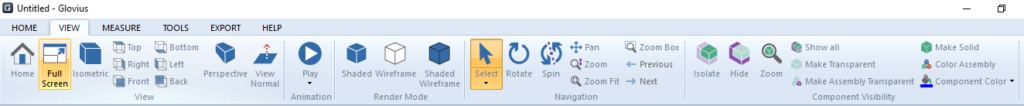
View
- Home – Set the view to default orientation
- Full Screen – Toggle full screen mode
- Isometric – Set isometric view
- Top – Set top view
- Right – Set right view
- Front – Set front view
- Bottom – Set bottom view
- Left – Set left view
- Back – Set back view
- Perspective – Set perspective projection
- View Normal – Click to view normal at the point
Animation
Play animation with standard views and model views
Render Mode
- Shaded – Set shared render render mode
- Wireframe – Set wireframe render mode
- Shaded Wireframe – Set shared wireframe render mode
Navigation
- Select – Click entity to select
- Select Box – Select components in the specified box
- Rotate – Rotate the component
- Spin – Select a point and rotate the component along the specific axis
- Pan – Pan the component
- Zoom – Zoom In/Out of the component
- Zoom Fit – Fit the component in render area
- Zoom Box – Zoom the component to specified area
- Previous – Go to previousw
- Next – Go to next view
Component Visibility
- Isolate – Select a component to view and hide others
- Hide – Select a component to hide it
- Zoom – Select a component to zoom into it
- Show All – Show all components
- Make Transparent – Select a component to apply transparency effect
- Make Assembly Transparent – Select an assembly to apply gradient transparency to its components
- Make Solid – Select a component to make it solid
- Color Assembly – Apply color to assembly
- Component Color – Select a component to apply color
Measure
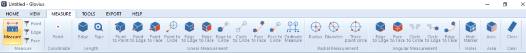
- Measure – Measure a point, line and face
- Point Filter – Activate point filter
- Edge Filter – Activate edge filter
- Face Filter – Activate face filter
Coordinate
Point – Measure the coordinates of point
Length
- Edge – Measure the length of edges
- Tape – Measure the total length of selected edges
Linear Measurement
- Point to Point – Measure the distance between two points
- Point to Edge – Measure the distance between a point and an edge
- Point to Face – Measure the distance between a point and a face
- Point to Circle – Measure the distance between a point and the center of circle
- Edge to Edge – Measure the distance between two edges
- Edge to Face – Measure the distance between an edge and a face
- Edge to Circle – Measure the distance between from an edge to circle center
- Circle to Circle – Measure the distance between center of two circles
- Face to Face – Measure the distance between two faces
- Face to Circle – Measure the distance between a face to circle center
- Ordinate Measure – Continually measure the ordinates of selected entities
Radial Measurement
- Radius – Measure the radius of the circle
- Diameter – Measure the diameter of the circle
- Three Point Circle – Measure the radius of the circle drawn from three points
Angular Measurement
- Edge to Edge – Measure the angle between two edges
- Face to Face – Measure the angle between two faces
- Circle to Circle – Measure the angle between the axis of two circles
- Circle to Edge – Measure the angle between the circle axis and an edge
- Edge to Face – Measure the angle between and edge and a face
Hole
Hole Marker – Show the hole information
Area
Measure the total area of selected faces
Clear
Clear all measurement
Tools
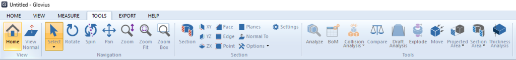
View
- Home – Set the view to default orientation
- View Normal – Click to view normal at the point
Navigation
- Select – Click entity to select
- Select Box – Select components in the specified box
- Rotate – Rotate the component
- Spin – Select a point and rotate the component along the specific axis
- Pan – Pan the component
- Zoom – Zoom In/Out of the component
- Zoom Fit – Fit the component in render area
- Zoom Box – Zoom the component to specified area
Section
- Section – Take a section along the axes
- XY – Take a section along XY plane
- YZ – Take a section along YZ plane
- ZX – Take a section along ZX plane
- Face – Take a section along a plane face
- Edge – Select coplanar edges to create a section
- Point – Create custom section using 3 points
- Planes – Create custom section on selected reference plane
- Normal To – View normal to active clipping plane
- Options –
- Plane – Toggle to show and hide section plane
- Cap – Toggle to fill open edges at section plane
- Flip – Toggle to flip the section plane direction
- Outline – Toggle to show outline of section
- Hatching – Cross section hatching
- Settings – Change section setting
Tools
- Analyze – Select a component to get a quick overview
- BoM – View bill of materialCollision
- Analysis – Check collision among all components in the assembly
- Compare – Select two variants of a model to compute differences in 3D geometry
- Draft Analysis – Perform draft analysis for the part
- Explode – Disassemble the components to view its structure
- Move – Select a component to move it in the scene
- Projected Area – Compute a projected area along a face
- Section Area – Compute a section area along a face
- Thickness Analysis – Perform thickness analysis of part
Export
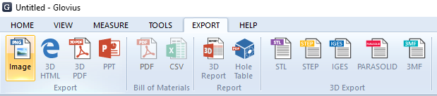
Export
- Image – Export file in image
- 3D HTML – Export file in 3D HTML
- 3D PDF – Export file in 3D PDF
- PPT – Export views of model in PPT
Bill of materials
- PDF – Export Bill of Material to PDF
- CSV – Export Bill of Material to CSV
Report
- 3D Report – Generate 3D report which contain 3D PDF model and bill of material
- Hole Table – Generate a hole table report.
3D Export
- STL – Export file in STL
- STEP – Export file in STEP
- IGES – Export file in IGES
- PARASOLID – Export file in PARASOLID
- 3MF – Export file in 3MF
Help
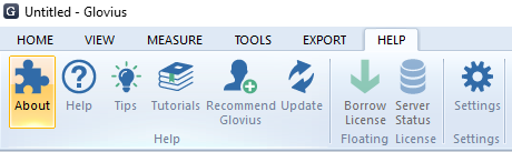
Help
- About – Open About dialog box where user can configure the Glovius license.
- Help – Get online help of Glovius
- Tips – Show Glovius tips
- Tutorials – View Glovius video tutorials online
- Recommend Glovius – Recommend Glovius to your friend
- Update – Check for Glovius product update
Floating License
- Borrow License – Borrow floating license for 7 days
- Server Status – Shows the list of users who are using server license
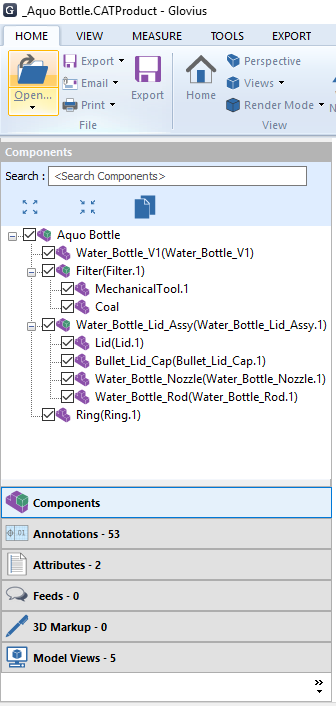
Accordion Elements
Components – View defined components in component tree. User can hide/show certain components.
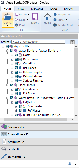
Annotations – List of predefined annotations or pmi data from original file.
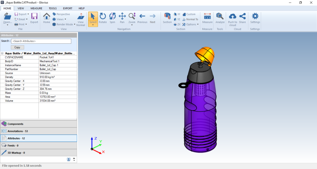
Attributes – Details of characteristics of selected components.
Feeds
Add comment for model which will sync with model in cloud account.
3D MarkUp
List 3D markups added in Glovius.
Model Views
List of predefined model views from original file.