Wall Thickness Analysis of CAD Parts
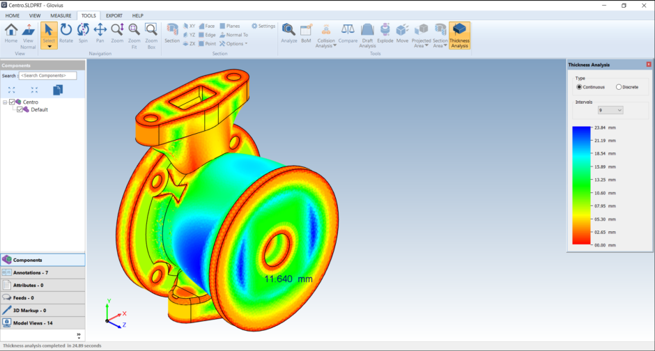
The thickness analysis tool analyzes the material distribution in the part and displays the results visually. Identifying the thick and thin regions helps you optimize the part design. Thin regions may fail during usage and thick regions increase material costs.
The ability to determine the material distribution and the corresponding thickness or thinness of a casting part is crucial for its design and manufacturing. Non optimal values of the part leads to issues in its performance during use. Thin wall sections may be structurally weak causing the component to fail while over compensated thick portions lead to an increase in the weight of the component and hence the subsequent cost to manufacture.
Perform Wall Thickness Analysis
Perform thickness analysis of CAD parts using Glovius.
Click on Thickness Analysis button in the Tools ribbon to start.
After a while, you will see the results of the analysis on the component.
Hover over any point to quickly see the values on the model.
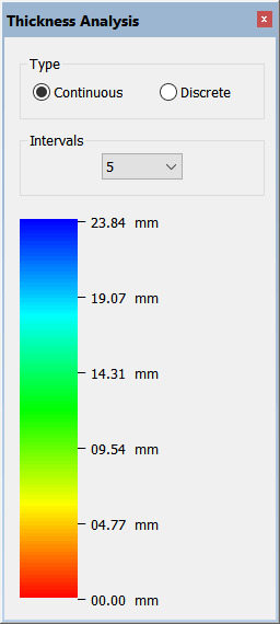
On the right, you can change the banding, between Continuous and Discrete. You can also select the number of intervals.
With Discrete bands, you can also edit the band upper and lower bounds by clicking on the number. Specify your band values for a customized look at the wall thickness analysis.
Ray and Sphere Method
In Glovius, wall thickness analysis can be performed using the Ray method or the Sphere method. You can choose either method from the Glovius Settings Dialog.
Ray method is typically suitable for finding thin wall sections and helps detect edges. Sphere method is useful for identifying thick sections that may warp or deform during casting process.
Video Tutorial
Watch a video tutorial of Wall Thickness Analysis feature in Glovius.